This challenge provided task.bin an ELF.
task.bin: ELF 32-bit LSB executable, Atmel AVR 8-bit, version 1 (SYSV), statically linked, not stripped
Whoa! AVR! Lucky for us it’s 1. an ELF and 2. not stripped.
Popping it into IDA and manually selecting “Atmel AVR” as the CPU I was happy to see demangled C++ function names as well as global symbols. Looking at the globals there were a few of note: i, int_recorded, buttonState, and Serial. OK, this clearly expects input from the GPIOs and/or over serial.
Looking at the functions, there were a few to reinforce my hypothesis: HardwareSerial::read for one. Although I didn’t see anything that showed GPIOs being read, this wasn’t too big of a deal: GPIOs are easily read just by reading from a certain register. There were a few that made me a little bit nervous: TIMER0_OVF specifically. If I had to deal with precise timing I would not have fun. The timers, however, are probably used to keep the serial clock.
Without a main function I started my analysis at __RESET. Thanks to the labels I was able to easily skip most of the function, which was just clearing our the .bss segments. Looking at where the ‘function’ ‘ended’, I found a jump to, basically, an infinite loop, and just before it a call to sub_2D4. This is main.
I started in main but was quickly overwhelmed with what was going on. I am not familiar with the instruction set, and since a lot of it is configuration, I would have to constantly refer to the datasheet. I needed something faster.
Now the AVR is a series of microcontrollers that is ubiquitous in electronics. Your TV’s remote might have one (though it’s likely a PIC). They exploded in popularity, however, with the introduction of the Arduino. I had a hunch that this was an Arduino binary, so I decided to see what an arduino binary looks like in IDA.
I wrote up a simple ‘sketch’ that setup serial communication, sent and received a few bytes, and read input from a few GPIOs. My goal was to get the same set of functions and a similar setup to my mystery binary – This would let me find the common code and basically ignore it completely.
After figuring out where the damned ELF is written to when compiled (some temp folder), I popped it in IDA and was happy to see that the code was indeed very similar. micros, for example, was a function I thought I might have to reverse, but it turned out it was just the delay function. All I really needed to look at was main, and I could ignore most of the first basic block, as it was just serial setup.
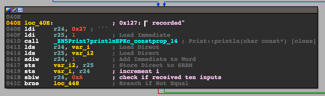
Since I figured the binary would send something out on the serial line I looked at the strings and found three that mattered: " recorded”, “Wrong flag”, and “Right flag”. Easy! Just find the Xrefs and trace back to find how to reach either!
This is where I hit another snag: No Xrefs. Come to think of it, I couldn’t find an xref to any of the globals I found. There was a reason for this. Two actually:
- AVRs use a Harvard Architecture. That means that they have two address spaces. One for code (read off of the internal flash) and one for data. The CPU knows which to use simply by context: Branch instructions use the code address space, sram reads use the data. This was messing up IDA, since it expects one. Whoever made the AVR CPU module for IDA handled this: The data segment was mapped to start at 0x800000. This means that my globals appeared way higher than they really were:
buttonStatewas shown as 0x800168 but was actually at 0x168. - AVRs are 8-bit micros. This means that the registers (most) are only 8 bits long. This means that they can’t even hold an entire address! This is solved with special instructions that expect an address across two registers.
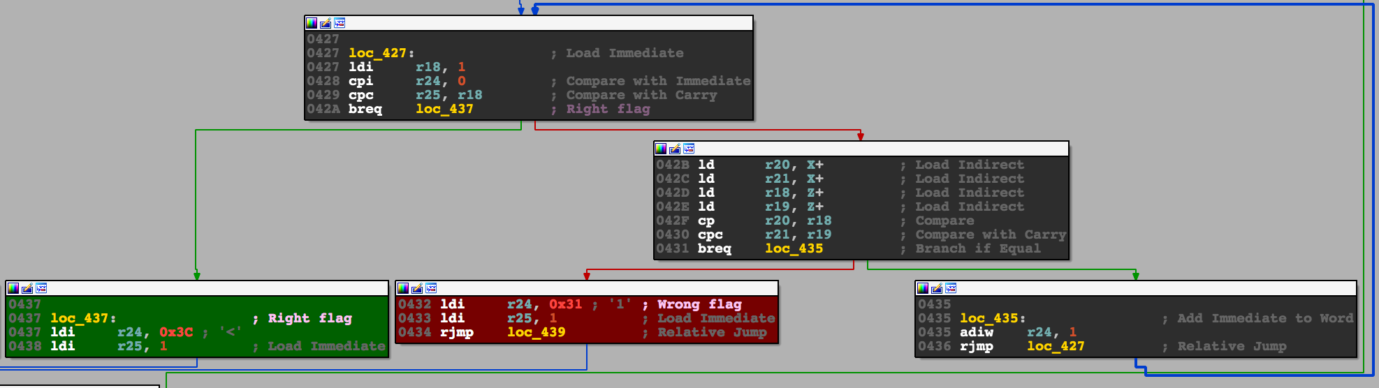
Armed with this knowledge I was able to find the xrefs. I just had to look for code that wrote two immediates into two registers that, when appended to eachother, formed the 16-bit address I was looking for. Skimming through the code I quickly found what I was looking for: The branch to “Right flag” at 0x42A.
Despite knowing where I needed to get to, I had a very hard time figuring out where the input was read: It was time to go dynamic.
Simavr is a great little AVR emulator and I could not have solved this challenge without it. While there’s a CLI to run hex files, what I wanted (gpio and serial) was a little bit more involved. Luckily there were examples that did what I needed. Guessing that the AVR was an atmega328 (an AVR used commonly in the Arduino) it was little trouble combining the examples and adding a few tweaks to get it running. Using cu to connect to the tty that simavr created I could see the output:
0 recorded
0
0
...
I tried to send text over serial but it appeared to be non responsive. I ended up writing code to randomly press GPIOs, but I don’t think it worked at all, what I needed was a debugger. Luckily this is another thing that simavr supports! My simulation code can be found here.
Installing avr-gdb (with brew) and setting up simavr to setup a gdb server I could connect. Only issue was that breakpoints didn’t work! After some struggling I found two peculiarities:
- You cannot set a breakpoint on a specific address. GDB will add 0x800000 (like IDA does) but this is out of the address space and will never hit. You can get around this by setting PC-relative breakpoints e.g.
b *($pc + 0x2c). - For some reason the addresses in GDB are double what you see in IDA. I found this by setting random traps (which do work) and correlating the GDB address with the address in main.
This meant that if I wanted to set up a breakpoint in GDB I had to:
- Find the target address in IDA and double it.
- Find the current PC in GDB.
- Subtract the two numbers and Use the offset to set the bp
b *($pc + <offset>).
Now it was a matter of forcing the code path to go towards the prints I wanted. I set up breakpoints at the conditional branches at 0x3F4, 0x3F8, 0x41C, and 0x431. At each point I simply set the appropriate register or status flag to take the branch I wanted. The branch at 0x431 is hit in a loop, each time after doing a series of comparisons. If any fail the badboy message is printed. These checks are what I need to pass. The check before that, at 0x41C, checks that some variable is 10. Since the flag format for this challenge was 10 numbers, this is clearly a check that enough have been reported.
I got around these by faking the number of report values to 10 at the 0x41C check. The badboy check I got around by setting up a command on the breakpoint to automatically dump the registers (info reg or i r), set the zero flag in the status register to pass the check (set $SREG = 0x37 has this bit set and didn’t mess with the others), and then continuing. I then looked at the values in r18 and r19, that were printed out, appended them (print r19<<8 + r18), and submitted.
Flag: 307, 908, 621, 588, 332, 515, 546, 605, 863, 90
Last modified on 2016-11-18